 6 dB attenuator.
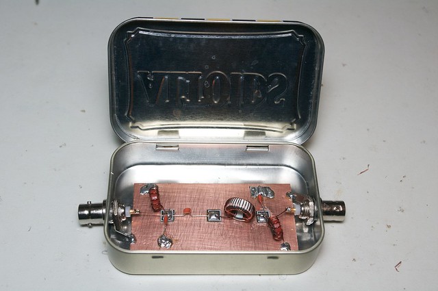
 20 dB attenuator.
author: Daniel Hjort date: 2014/01/19 location: Tokyo, Japan tags: rf, radio, power, termination, impedans, scope, modules, attenuator, returnloss, vswr
Here are some basic theory and techniques you need to know when starting with RF experimentation. Most of it I have picked up reading The Popcorn Site. The RF Workbench pages there are a very good resource to learn about this stuff.
It is convenient to measure signal power in dBm. 0 dBm is 1 mW. It makes it easy to calculate attenuations and amplifications, as they can be expressed as sums and not products. When translating dBm (power) to V (electric potential) we need to know the load impedans.
Here's a conversion table:
| dBm | W | Vpp@50ohm | Vrms@50ohm |
|---|---|---|---|
| 30 | 1 | 20 | 7.07 |
| 20 | 100m | 6.32 | 2.24 |
| 10 | 10m | 2 | 707m |
| 6 | 4m | 1.26 | 446m |
| 3 | 2m | 893m | 316m |
| 0 | 1m | 632m | 223m |
| -3 | 500µ | 448m | 158m |
| -6 | 250µ | 317m | 112m |
| -10 | 100µ | 200m | 71m |
| -20 | 10µ | 632m | 224m |
| -30 | 1µ | 20m | 7.07m |
In RF work 50 ohm termination is standard. It is convenient to build separate modules all with 50 ohm terminated ports.
Also set your signal generator to 50 ohm output impedans and 50 ohm terminate your scope. An easy way to do the latter is to put a BNC-T on the scope and 50 ohm terminator on one of the branches and use the free one to connect whatever you want to measure.
Now it's easy to convert Vpp to dBm and if you connect your signal generator directly to the scope the measured amplitude will be the same as the amplitude settings on the generator.
Sometimes the signal you have is too strong for whatever you need to feed it into. PI-network attenuators are then useful to reduce the power of the signal. How much the signal is attenuated is measured in Decibel (dB).
          R3
*----*---[====]---*----*
     |            |
     #            #
In   # R1         # R2  Out
     #            #
     |            |
*----*------------*----*
| dB | R1, R2 | R3 |
|---|---|---|
| -3 | 292 | 17.6 |
| -6 | 150 | 37.4 |
| -10 | 96.3 | 71.2 |
| -20 | 248 | 61 |
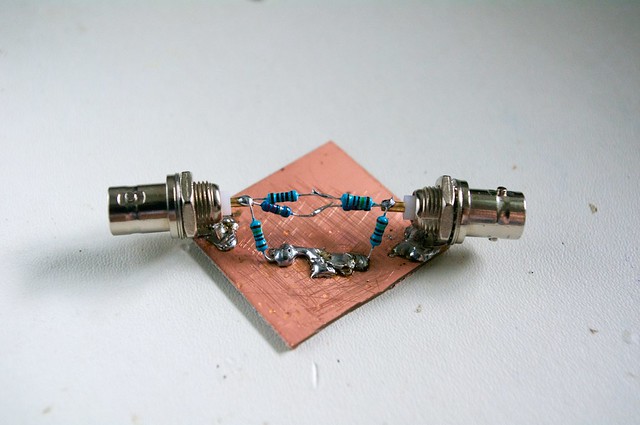
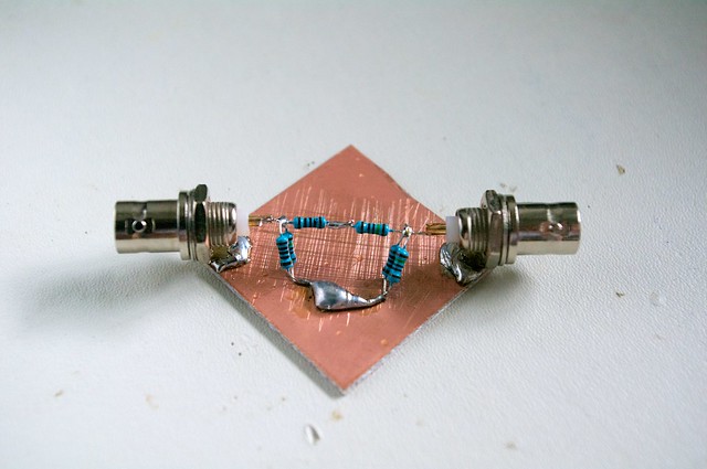
The table show a few possible attenuators with 50 ohm input and output impedans. Note that some of them only show 50 ohm on the input with 50 ohm on the output.
6 dB attenuator.
20 dB attenuator.
As an example say we have a signal that is 3 dBm (2 mW) and feed it through a -6dB attenuator. The signal appearing on the other side is then -3 dBm (0.5 mW). Remember the attenuated power gets dissipated as heat so make sure your resistors can handle the power you need.
We have seen that impedans matching (and a 50 ohm standard) make power calculations and measurements easier. Another reason the strife for impedans matching is that it maximises the transfered power. If there is a impedans mismatch some of the signal power will be reflected back to the source.
PI-network attenuators can be designed to have different input an output impedans and can be used for matching. Even simpler 2 resistor L-pads can be used as well. Of course this approach will also cause big power losses.
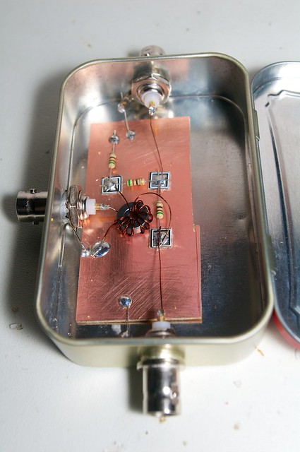
An other method is using broadband transformers. Generally wound on toroids they give a 1:n2 impedans ratio for a 1:n windings ratio.
What if we don't know the input impedans of something we need to interface to. How would we know if it's a match. We can always send a RF signal into it and see how much is reflected. If the impedans match is perfect zero power is reflected. How can we measure the reflected power? For that a return loss bridge is used.
To measure return loss everything is connected up like this.
/-----------\                   /--------\
| Signal    |                   | Return |                   /-----\
| Generator |----50 ohm Coax----| Loss   |----50 ohm Coax----| ??? |
\-----------/                   | Bridge |                   \-----/
                                \--------/
                                    |
                                50 ohm Coax
                                    |
                               /---------\
                               |  Scope  |
                               \---------/
Fire up the signal generator on a desired frequency and note the signals power on the scope with the mystery load disconnected. Then connect the mystery load and again note the signals power on the scope. The return loss is the ratio of these numbers. The ratio in dB between two measured values in dBm is the difference between the two measured values.
Return loss is related to the Voltage Standing Wave Ratio VSWR. When a part or all of the signal is reflected back a standing wave is created. The voltage at the resulting standing wave's peaks and troughs is measured and the ratio is calculated so it is a number between 1 and infinity (or strictly undefined). An open ended coax give a infinite impedans so all power is reflected back. The trough voltage of the standing wave is 0 and the peak is double the peak voltage of the incident signal. This is the worst case and the VSWR is "infinite". The VSWR is also the same as the ratio between the impedans of the line and the load.
VSWR = if Zload > Zline Zload/Zline
       if Zline < Zload Zline/Zload
       else 1

VSWR = [10^(RL/20) + 1] / [10^(RL/20) - 1]
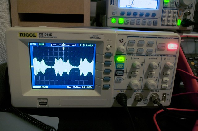
40m band pass filter sweeped. Weird shape cause it wasn't properly terminated.
 40 meter BPF.
A technique used to prototype RF-circuits. Related to Ugly-construction but uses pads glued to the board to create islands.
Ferrite and powdered.
Magnetic wire.
TBD
[ IndexPage | Edit on Github | Powered by PotBliki | © 2010-2014 Daniel Hjort - CC BY-SA 3.0 | http://danielhjort.net ]